Zyqora
Choosing a 40G QSFP+ transceiver is not just a matter of matching port speeds. The module must also suit the fiber, link distance, switch, and operating environment. A mismatch can leave a link dark, unstable, or slower than expected. Small details matter.
Start with the equipment datasheet. Confirm that the switch supports the module type and, where required, its vendor coding. Then check the fiber already installed. A QSFP-40G-SR4 is commonly used with multimode fiber for short links; typical reach is up to 100 meters on OM3 or 150 meters on OM4. For longer single-mode connections, a QSFP-40G-LR4 can support links up to 10 kilometers under specified conditions. Actual performance depends on the full optical path, including connectors and patch panels. Not just distance.
Also consider connector type, wavelength, power consumption, and temperature range. In a crowded rack, heat and airflow deserve attention, especially when many ports run at once. Digital diagnostics can help track temperature and optical levels, but they do not replace proper testing. Before ordering, compare the module’s specifications with both ends of the link and verify the cable route. Two similar-looking transceivers may use different optics. That is easy to miss. A careful choice reduces avoidable troubleshooting, although no checklist can remove every installation surprise. I would still confirm compatibility with the equipment vendor when the network is business-critical.
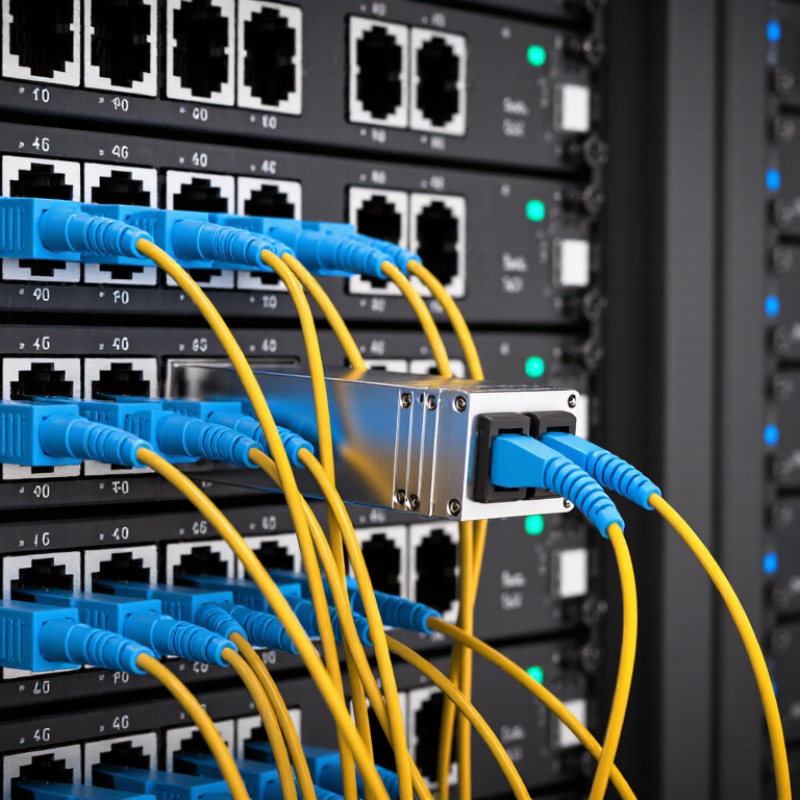
Before choosing a 40G QSFP+ transceiver, define the link’s actual job. Note the required distance, fiber type, connector, and whether the switch supports the intended module. A 12-meter link inside one rack has different needs from a 2-kilometer campus run. Also check whether the link must break out into four 10G connections; compatible port configuration matters.
The Ethernet Alliance’s 2024 Ethernet Roadmap charts Ethernet speeds from 1GbE through 1.6TbE, placing 40GbE within a much broader capacity landscape. That context makes it worth checking expected traffic growth, not just today’s utilization. IEEE 802.3ba specifies 40GBASE-SR4 for up to 100 meters on OM3 fiber and 150 meters on OM4; 40GBASE-LR4 supports up to 10 kilometers over single-mode fiber. These figures are useful limits, not a substitute for checking the complete link budget.
Distance is not the whole story. Confirm the installed fiber grade, patch-panel path, connector polarity, and the far-end optic. SR4 typically uses MPO connectivity, while LR4 commonly uses duplex LC. Small details can stop a link from coming up. It is easy to focus on the transceiver label and overlook the plant in between; that is often where the real uncertainty sits.
Choosing a 40G QSFP+ transceiver starts with the fiber already installed. Multimode fiber suits short links inside data centers. A 40GBASE-SR4 module commonly uses OM3 or OM4 fiber with an MPO connector, reaching up to 100 or 150 meters, respectively. Check the module’s specification; those limits depend on the fiber grade and link conditions. Measure the route, not just the distance between racks.
For longer runs, single-mode fiber is usually the better fit. A 40GBASE-LR4 module typically uses duplex LC connectors and supports links up to 10 kilometers over single-mode fiber. Other single-mode QSFP+ options may use MPO connectors and have different distance limits. Connector shape alone does not confirm compatibility. The optical standard, fiber type, and transceiver must all match.
Check the patch panel and cable ends before ordering. An MPO link also needs correct polarity, and a mismatched trunk can leave a link dark even when the modules appear right. I still double-check the route and connector details; the label on an old cable may not tell the whole story. Keep a little margin below the rated reach when planning a link, especially when its path includes several patch points. One overlooked detail can cost a site visit.
When comparing 40G QSFP+ transceiver types, start with fiber and reach. QSFP+ SR4 uses 850 nm light over multimode fiber and an MPO connector. It typically supports up to 100 meters on OM3 or 150 meters on OM4. That makes it practical for short links between racks. Check the fiber grade and connector polarity; a mismatch can leave a link dark.
For longer runs, QSFP+ LR4 sends four wavelengths near 1310 nm over single-mode fiber, usually through duplex LC connectors. Its typical reach is 10 kilometers. PSM4 also operates around 1310 nm, but uses parallel single-mode fibers and MPO connectors, commonly reaching 500 meters. The connector choice matters as much as the wavelength. They are not interchangeable designs.
BiDi QSFP+ modules can carry 40G over duplex multimode fiber using two wavelengths, often near 850 nm, rather than four parallel lanes. They can reduce fiber count, but both ends need compatible wavelength directions. Small detail. Before buying, confirm the module’s reach, fiber type, connector, and host-device support. I would also check the actual route length, including patch panels. Specifications look clean on paper; cable paths are less tidy.
Before choosing a 40G QSFP+ transceiver, check the switch’s hardware guide and compatibility matrix. Confirm the supported module type, port mode, firmware requirements, and whether the port accepts third-party optics. The connector and fiber must match too. IEEE 802.3ba specifies 40GBASE-SR4 for up to 100 meters over OM3 fiber or 150 meters over OM4; it uses an MPO interface. 40GBASE-LR4 supports links up to 10 kilometers over single-mode fiber, typically with duplex LC connectors. Close enough is not enough.
Operating conditions matter just as much. Check the module’s specified temperature range against the rack’s actual inlet temperature, not the room thermostat. Review airflow, power limits, and port density; tightly packed optics can run warmer than an isolated test setup. The QSFP+ MSA defines the module interface, but it does not guarantee that every host handles every optic identically. Check diagnostics and link settings as well. Small details count.
A useful field check is to compare the optic’s reach, fiber type, wavelength, and host support before installation. Then inspect the fiber ends and verify link status after insertion. IEEE 802.3ba provides the physical-layer distances; the module datasheet provides its operating limits. I would not treat a successful link on a test bench as proof of stable operation in a hot rack. That assumption is easy to make, and worth revisiting.
A 40G QSFP+ module is only a good fit when its optic, fiber, and connector match the installation. IEEE 802.3ba specifies 40GBASE-SR4 operation over parallel multimode fiber, with nominal reaches of 100 meters on OM3 and 150 meters on OM4. That means checking the fiber grade and polarity before inserting the module, not after the link fails. Inspect MPO end faces with a fiber scope; a tiny speck can disrupt one lane while the others still appear healthy. Check the host port’s supported module type, too. Compatibility is not always obvious from the cage shape.
Plan monitoring and testing around the link’s actual path. IEEE 802.3ba also defines 40GBASE-LR4 for reaches up to 10 kilometers over single-mode fiber, so confirm the optic type and optical budget at both ends. Record receive and transmit power, temperature, and alarm status after installation, then compare readings over time. Use an optical power meter and, where appropriate, a calibrated light source to verify loss; a link-up light alone proves little. For SR4, test each fiber lane and confirm polarity through the full channel. Labeling helps later. I have seen teams skip it, then spend more time tracing strands than fixing faults. One detail is easy to miss: test with the same patching arrangement the live link will use. IEEE 802.3ba provides the interface limits, but the installed channel still needs its own measurements.
Confirm the link distance, fiber type, connector, and host-device support. Also check whether the port needs to break out into four 10G connections.
It typically reaches 100 meters on OM3 fiber or 150 meters on OM4. It uses multimode fiber and an MPO connector. Check polarity, too.
LR4 typically supports up to 10 kilometers over single-mode fiber. It commonly uses duplex LC connectors and four wavelengths near 1310 nm.
PSM4 uses parallel single-mode fibers and MPO connectors, typically reaching 500 meters. The connector and fiber layout differ, so the designs are not interchangeable.
Yes. BiDi can carry 40G over duplex multimode fiber using two wavelengths. Both ends need compatible wavelength directions.
Check fiber grade, connector polarity, patch-panel routing, and the far-end optic. Inspect MPO end faces; a speck can affect one lane. Easy to miss.
Measure optical loss with an optical power meter and a suitable calibrated light source. Test each SR4 lane and use the same patching arrangement as the live link.
Record transmit and receive power, temperature, and alarm status. Compare readings over time. A link-up light alone proves little, though teams sometimes treat it as enough.
Choosing the right 40G QSFP+ transceiver starts with defining the link’s requirements, including expected bandwidth, network layout, and the distance between devices. Next, match the fiber type and connector to the existing cabling, and confirm that the transceiver’s supported transmission distance is suitable for the installation. Comparing available transceiver types and wavelengths can help identify an option that fits the link design and fiber infrastructure.
Before installation, verify that the transceiver is compatible with the equipment and can operate within the site’s temperature and other environmental conditions. Consider how the module will be installed and monitored, and plan to test the link after deployment. Checking signal performance and connection stability can help confirm that the 40G QSFP+ link is working as expected and make it easier to identify issues early.